


How much do you know about these calculation formulas for water pumps? Let's take a look together
Release Time: 2023-08-23
Water pump piping long and short
In the pipeline system, the local head loss only accounts for less than 10% of the head loss along the way, or when the length of the pipeline is greater than 1000 times the pipe diameter, the local head loss and the outlet velocity head can be omitted in the hydraulic calculation, which is called a long pipe; otherwise called short tubes. In the hydraulic calculation of the short pipe, the local head loss and the pipe flow velocity head should be calculated.
Calculation formula of head loss along the way
1. Darcy's formula (applicable to full flow in round pipes)
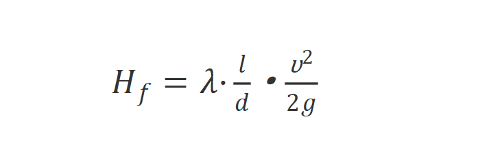
In the formula:
λ is the friction coefficient along the way (also recorded as Fanning friction coefficient in chemical industry), and its dimension is 1. λ is not a definite constant, λ is related to the Reynolds number Re and the relative roughness of the tube wall ∆/d, that is, λ=f(Re, ∆/d), but for the laminar flow motion of the circular tube, λ is only related to the flow state , λ=64/Re.
l—pipe length, m;
D—pipe inner diameter, m;
v—average velocity, m/s;
g—gravitational acceleration, m/s²
Calculation formula of drag coefficient along the way
(1) Kohlbrok-Zion formula
(2) Hazen-Wllliams formula
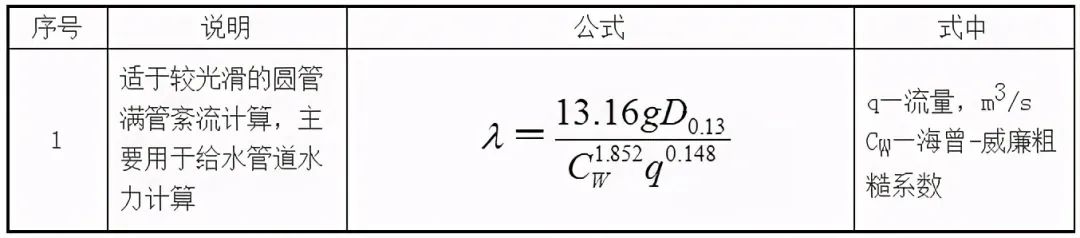
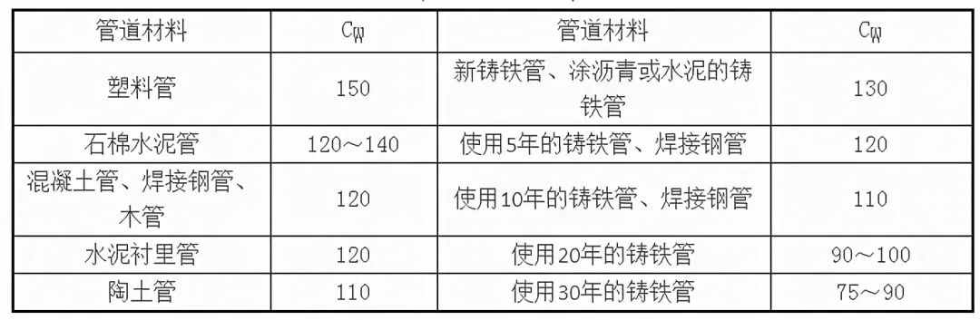
Hazen-Wllliams roughness coefficient
(3) Colebrook-White formula
The Cole Brock-White formula is suitable for various turbulent flows and is one of the formulas with high applicability and calculation accuracy. The formula is:
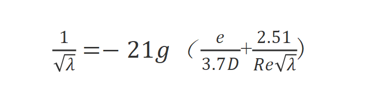
In the formula:
λ is the friction coefficient along the way (also recorded as Fanning friction coefficient in chemical industry), and its dimension is 1. λ is not a definite constant, λ is related to the Reynolds number Re and the relative roughness of the tube wall ∆/d, that is, λ=f(Re, ∆/d), but for the laminar flow motion of the circular tube, λ is only related to the flow state , λ=64/Re.
D—pipe inner diameter, m;
V—average velocity, m/s;
e—equivalent roughness of pipe wall, m;
ν—kinematic viscosity, ㎡/s
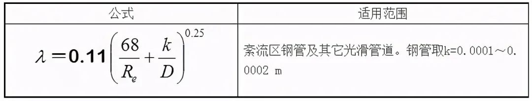
(4)
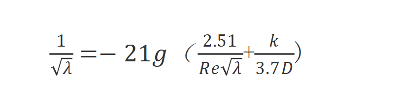
In the formula:
k—equivalent roughness of pipe wall, m;
D—pipe inner diameter, m;
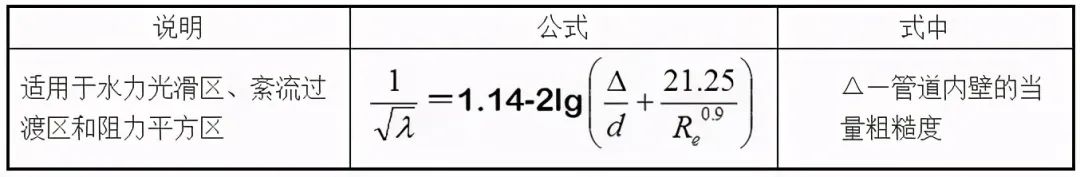
The area suitable for turbulent flow includes hydraulic smooth area, transition area (also known as turbulent flow transition area) and resistance square area.
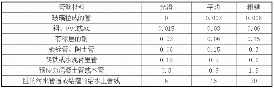
(5) Pipe wall roughness
Common pipe inner wall equivalent roughness e
Related Recommendations.

Leaders of Hebei Huitong Pump Industry led a team to Russia to investigate and deepen business exchanges and cooperation

Hebei Huitong Pump Industry participated in the first pump and motor exhibition in Anguo

Gap Adjustment for Overhaul of Water Pump Stator and Rotor Components

Common faults and maintenance methods of water pumps

Pump maintenance methods and precautions.


Online